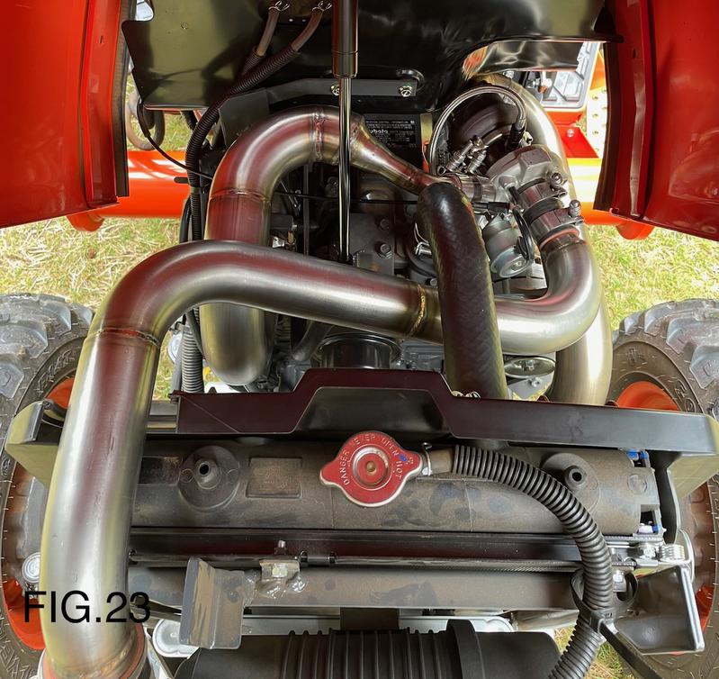
S2T Performance Products Tractor Turbo Systems
S2T Performance Products Kubota L2501 Turbo Kit Installation Instructions:
Thank you for purchasing the S2T Performance Kubota L2501 Bolt-on Turbo Kit. We hope that this Turbocharger system enhances the enjoyment and performance of your Tractor for years to come.
S2T Performance recommends purchasing and installing a Pyrometer (EGT probe) and EGT gauge prior to the Turbo Kit installation to monitor and record EGT and combustion temperatures before installing this Turbo Kit.
Disclaimer: Any risk associated with the installation of the Turbocharger system on a tractor are solely that of the tractor owner and S2T Performance Products is not liable for loss of warranty or any damage incurred to your tractor.
Installation;
Always refer to the OEM Kubota L2501 service repair manual and operator manual for proper procedure and torque specifications.
1). Remove Front Loader (per factory manual) if equipped.
Disconnect the negative batter terminal
2). Remove Hood (per factory manual)
3). Remove Engine Bay side panels
4). Remove muffler and exhaust pipe
5). Remove air cleaner Intake hose and clamps
6). Remove PCV hose (located on intake manifold and engine valve cover)
7). Remove Oil Pressure Sensor on left side of engine block
8). Replace Oil Pressure Sensor with the supplied 1/8" NPT 4AN Fitting and install into engine block (add small amount of high temperature Teflon sealant to threads)
9). Install supplied 4AN 90 degree Elbow Fitting to 4AN fitting on engine block (add small amount of Teflon high temperature sealant to threads)
10). Install Oil Pressure Sensor in supplied 4AN Sensor Port Fitting and connect to 90 degree 4AN elbow (add small amount of high temperature Teflon sealant to threads)
11). Attach Turbocharger to Turbo Exhaust Manifold Adapter using supplied bolts (add small amount of anti-seize to threads) and OEM gasket (pre-assembled by S2T)
12). Attach Turbo down-pipe/exhaust to Turbocharger using supplied bolts (add small amount of anti-seize to threads) and OEM gasket (pre-assembled by S2T)
13). Install the complete Turbocharger assembly to engine exhaust manifold using supplied bolts (add small amount of anti-seize to threads) and OEM gasket
14). Install supplied steel braided 4AN oil feed hose assembly to Turbocharger and 4AN sensor port (add small amount of high temperature Teflon sealant to threads). We found it best to route the hose through engine lift hook
15). Remove oil plug from left side of engine block
16). Install supplied steel braided 6AN oil drain hose assembly to Turbocharger assembly, connect the 6AN engine block fitting to hose and install the complete hose assembly in engine block drain hole by pressing into engine block (add small amount of high temperature Teflon sealant to threads).
17). Install supplied PCV plug on intake manifold, install clamp
18). Install supplied PCV hose and clamp to engine valve cover
19). Install Turbo Intake pipe to OEM air cleaner using supplied silicone hoses (Part #2726 & #2706) and clamps (Part #2788 & #2791). You may need to trim silicone hoses for proper fitment
20). Connect PCV hose to Turbo Intake pipe using additional PCV hose clamp. You may need to shorten PCV hose for proper fitment
21). Install Turbo Charge pipe to intake manifold using supplied silicone hoses (Part #2700 & #2708) and clamps (Part #2787 & #2792). You may need to trim silicone hoses for proper fitment
22). Check and make sure all bolts and connections are installed correctly and are tight. Disconnect the top Turbocharger feed AN hose and add a small amount of engine oil to the Turbocharger for the initial start-up.
23). Reconnect the negative battery terminal and start the Tractor and let idle. Check for leaks
24). Remove 6AN drain hose from engine block and ensure oil flow from Turbocharger. You may want to have a small container to trap oil flow from Turbocharger. Turn off Tractor. Reinstall 6AN fitting/hose to engine block
25). Reinstall hood and hood side panels. Reinstall Loader (if equipped/needed)
26). Remove plug from Turbocharger Adapter and install an EGT probe to view and monitor your exhaust gas temperature
You will be expected to continue to monitor your EGT temperatures while the Turbo Kit is installed on your tractor. Engine health and engine tuning is your responsibility!!!
Your new S2T Performance Products Kubota L2501 Turbo Kit is now installed.
Congratulations!!!
Thank you for purchasing the S2T Performance Products IssPro Turbocator Boost/EGT Gauge Kit. This Gauge Kit is intended for operators to monitor critical Boost and EGT readings to ensure safe operation but, should not be used for ‘Tuning’ purposes. S2T Performance recommends using calibrated professional diagnostic gauges to properly ‘Tune’ your tractor’s performance.
1). Disconnect the negative battery cable.
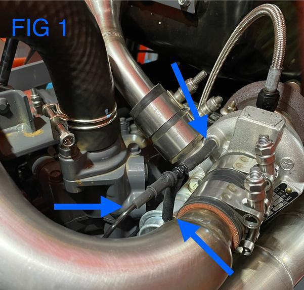
2). Remove OEM Mitsubishi Turbocharger vacuum hose and clamps located between the Turbocharger housing and actuator. See Fig 1
3). Install the supplied vacuum “T” assembly between Turbocharger compressor housing and boost actuator. See Fig 1
4). Insert the supplied vacuum hard line into the open end of the “T” fitting and run the vacuum line towards the firewall being mindful to keep the vacuum line away from “hot” engine components. See Fig 1
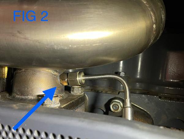
5). Remove the EGT plug/bolt located on the S2T Performance exhaust manifold Turbocharger adapter. See Fig 2
6). Install the EGT probe and secure with the included fitting(s). See Fig 2
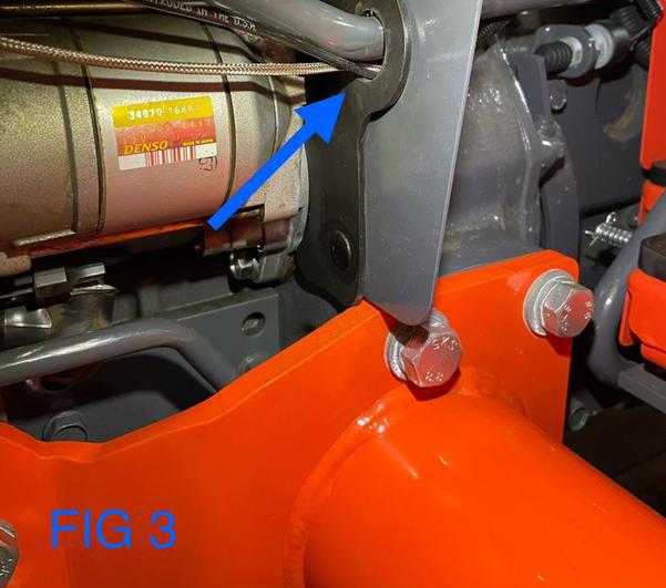
7). Run both the EGT probe wiring and vacuum hard line through the firewall access hole located near the starter. See Fig 3
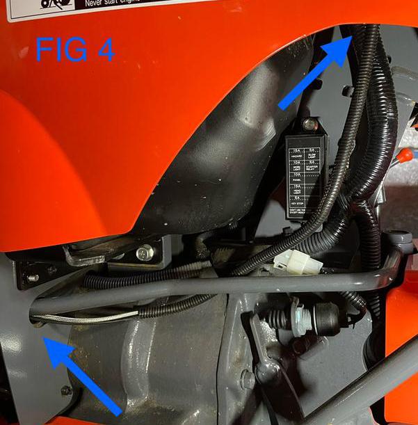
8). Insert/slide the EGT probe wiring and vacuum hard line into the supplied wiring conduit and route towards the steering wheel boot. See Fig 4
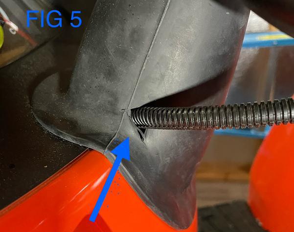
9). Using a sharp tool, make a small hole into the factory steering column boot and route the wiring up and through the hole. See Fig 5
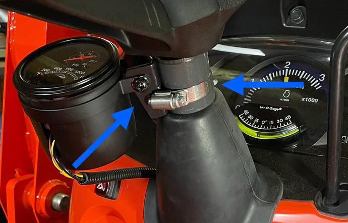
10). Unscrew the supplied hose clamp and position it around the steering column. Place the Autometer column bracket on the steering column and secure it with the hose clamp. Now, mount the Autometer gauge pod to the steering wheel column bracket and once positioned to your liking, tighten the Autometer pod bracket clamp and the hose clamp securely to the steering column. See Fig 6
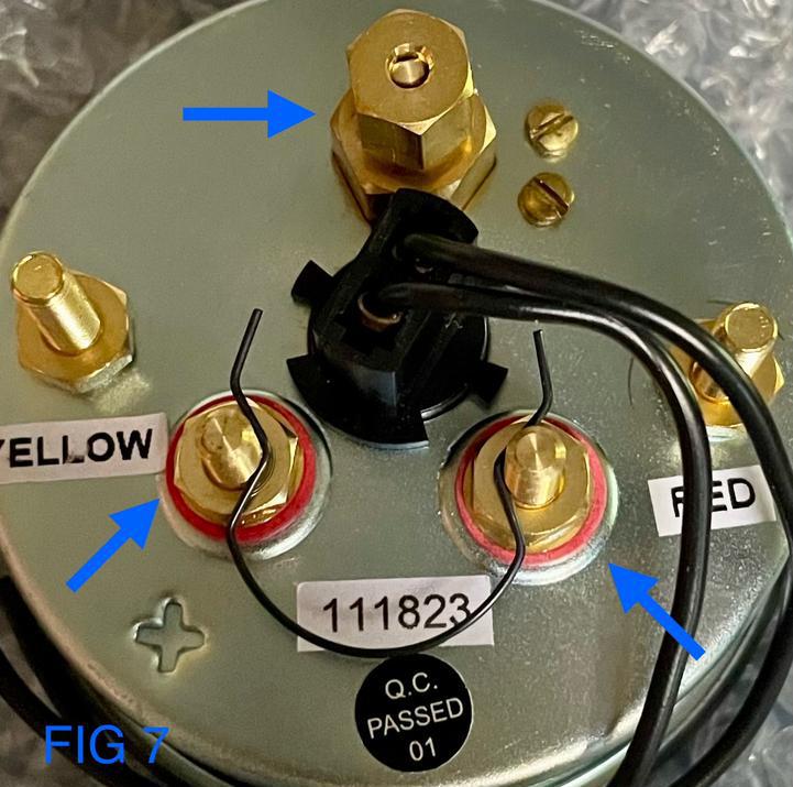
11). Install the vacuum hardline to the compression fitting on the IssPro gauge. Then, install the EGT probe wiring (Red/Yellow) to the correct terminals on the IssPro gauge as directed by the factory manual (optional - if you operate your tractor in dark conditions, you can connect the IssPro gauge light to your factory light switch following the instructions provided with the gauge). See Fig 7
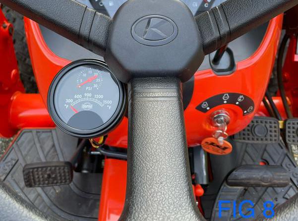
12). Insert the IssPro gauge into the Autometer gauge pod (you may need to add a couple pieces of electrical tape to the outside housing of the IssPro gauge to ensure a tight fitment) and reconnect the negative battery cable. See Fig 8
Congratulations!
Your new S2T Performance Products IssPro Turbocator Boost/EGT Gauge Kit is now installed and ready for you to monitor your tractor’s newfound performance!
OPTIONAL: S2T PERFORMANCE PRODUCTS ISSPRO GAUGE KIT INSTALLATION INSTRUCTIONS:


